Creating explosive visuals with the Visual Effect Graph


At Unite LA 2018 we unveiled the Visual Effect Graph, a tool for building real-time visual effects in Unity. The tool uses GPU run compute shaders, and a node-based workflow. This post compares the Visual Effect Graph to the existing Particle System, and shows how to get started with this powerful tool, now available through the Unity package manager for Unity 2018.3.
Inspired by the field of film visual effects, the Visual Effect Graph adapts many of the same powerful features for the creation of real-time visual effects.
Getting started
As of today, the Visual Effect Graph is available through the package manager for Unity 2018.3 or later. To install the Visual Effect Graph, navigate to Window > Package Manager > Advanced > Tick “Show preview packages” > Select “Visual Effect Graph” > Click Install
Currently, the Visual Effect Graph runs on the High Definition Render Pipeline in Unity 2018.3, with planned support for the Lightweight Render Pipeline coming in future releases. To start using the Visual Effect Graph, ensure your Unity Project is using the High-Definition RP.


To create a new Visual Effect, Right Click in the project window > Create > Visual Effects > Visual Effects Graph. After creating the Asset, drag it into the scene view or hierarchy.
The Visual Effect Graph window
Intended for everyone from VFX Newcomers to experienced VFX Artists and Programmers, Unity’s graph view uses Nodes and Blocks to provide a workflow that’s quick to learn yet powerful when mastered.
Contexts contain Blocks and represent the order of operations applied to the particles. Nodes connect together to perform a series of calculations that input into Blocks, which in turn define particle properties.
The Node system will be familiar to users who have used Unity’s Shader Graph tool, though not identical.
To create a Context or a Node press Space or right click and select Create Node outside of any Contexts. To create a Block press Space or right click and select Create Block while hovering your mouse over the Context.
Contexts


Systems are the collection of Initialize, Update and Output Contexts. It is represented by the dotted outline. Multiple systems can exist within the same Visual Effect Graph asset.
Spawn defines how many particles will be spawned, and with what timing (E.g. Periodic Burst, Constant, Single Burst).
Initialize starts with Capacity and Bounds:
Capacity determines how many particles from this System can exist at one time.
It’s important to note that Capacity allocates the appropriate amount of memory for the number of particles, and so this number should correspond to the amount that could be spawned. Often this can be calculated by:
Rate × Max Lifetime = Capacity
Bounds define the area that simulates the particle if seen by the camera.
Update changes particle properties over time and is the only Context which allows you to use forces. This is where you would apply collision, a Signed Distance Field, or Vector Field.
Output renders the particle, it determines what type of particle is spawned, the texture/colour, and its orientation. Final adjustments can be made to the particle’s size, position, etc. Each system can have multiple outputs, and each output can adjust most particle attributes.
Blocks


Blocks define particle properties, which can be overridden by Nodes. Blocks are contextual, and some Blocks cannot be used in certain Contexts. For example, a Spawn Rate Block can only be added to the Spawn Context.
Blocks can be disabled by un-ticking the checkbox to the right of the block name. Some inputs can be folded out with the small arrow to the left of the input name. This allows you to access specific attributes, for instance, the X, Y and Z components of a Vector3. .
Blocks and Contexts can be modified through the Inspector when selected in the graph. As such it can be very helpful to have the Inspector visible when authoring visual effects.


Nodes


Nodes have many functions, from outputting specified values and parameter data to performing a range of different calculations. Most nodes that define values, such as Add, Multiply or Lerp, can be modified to output different types of values, such as Float, Vector 3, or Color.
Workflow tools
Auto compile
By default, the Visual Effect Graph will recompile every time you change a Node or a Block. For smaller graphs, this enables you to quickly see your changes in the scene, but for more complex systems, compiling may take significantly longer. By disabling Auto Compile the graph will only compile when you save or hit the compile button, allowing you to make significant changes to the graph without having to wait after each adjustment.
Blackboard

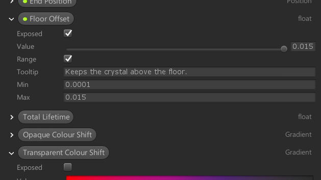
The Blackboard stores Parameters that you can use in the graph and expose to modify in the Inspector. To organize the many different types of Parameters you can create, the Blackboard supports Categories and Tooltips.
To create a new Parameter click the + icon in the top right of the Blackboard.


Target GameObject


The Target GameObject panel allows you to control the playback or view local-space gizmos of a specific instance of the currently opened visual effect in the scene view. To attach a GameObject, select an instance of the currently opened Visual Effect in the scene, and click Attach. Opening a Visual Effect directly from a scene instance will automatically attach it.
Parameter Binders


While exposed parameters can be set via script, Parameter Binders automatically configure parameters of a Visual Effect, for example, a GameObject’s position, scale, and rotation. To add a Parameter Binder, select your Visual Effect in the hierarchy, click Add Component, and search for “Binder”. Drag your GameObject into the box labeled “None”, then select the desired parameter by clicking the ⌄ symbol.
Comparison with the Particle System
The primary distinction between the two systems is the hardware on which they run. The Particle System is simulated on the CPU, whereas the Visual Effect Graph moves many of the calculations to compute shaders, which run on the GPU.


In this comparison we can see how the Visual Effect Graph has the advantage of simulating millions of particles, can compute complex simulations, and read frame buffers. On the other hand, the Particle System can use the underlying physics system and can be read back to interact with gameplay.
Another thing to keep in mind is device compatibility, as the required compute shaders are not currently supported on some devices, such as most mobile phones.
Supported data types
The Visual Effect Graph supports assets such as Point Caches, Vector Fields, and Signed Distance Fields These allow you to represent volumes, forces, collisions, and other custom data types.
- Point Caches store attributes of points in space, such as Transform, normals, colors, and UVs.
- Vector Fields push particles in 3D space after sampling the particle’s position.
- Signed Distance Fields can be used to both attract and collide particles using a volumetric representation.
An example of this would be authoring a skull signed distance field externally and then importing it into Unity to create a magical effect.
VFX Toolbox
The Visual Effect Graph team is developing a set of tools to generate these data types, known as the VFX Toolbox. Data created with the VFX Toolbox can also be used in conjunction within other areas of Unity, for example the Particle System.
The tool is available to download on GitHub.
Image Sequencer


Provides you with the means to process sequences of images, and generate texture Assets such as flipbook texture sheets.
Point Cache Bake Tool


Also known as pCache Tool, it generates 2D or 3D point caches from textures or meshes respectively.
Tips and tricks
The Visual Effect Graph has many powerful synergies and nodes that can make your effects more dynamic.
Sticky Notes, Node Groups, and Names
The Visual Effect Graph has a few useful features to help you comment and label your graphs.
Context Names allow you to name contexts, just double click the small section below the Context title.
To create a System Name, double click the small section below the top of the dashed outline.
Sticky Notes create resizable text boxes. To create a Sticky Note right click in an empty area of the graph, and select Create Sticky Note. There are 4 options for text size ranging from Small to Huge. To change the text size, right click a Sticky Note and select a size from the drop-down list. To resize a sticky note, drag any of the edges or corners.
Node Groups allow you to title a group of nodes, and move them as one. To create a node group, select a group of nodes, right click the top of a selected node, and select Group Selection. To move a node into a node group, drag it inside an existing group. To move a node out of a group, hold the Shift key and drag it out. To delete a group without deleting the nodes, click the group title once so that it’s highlighted, and press the delete key.
Spawner chaining


Spawner chaining allows one spawner to start or stop another. Simply take the output of a Spawn Context and connect it into the Start or Stop. The above example spawns a constant stream for 2 seconds, stops for 2 seconds, then repeats.
GPU Events


GPU Events allow you to trigger another particle system under custom conditions or the death of a particle. The above example will spawn between 10 and 15 particles on the death of a particle.
To enable GPU Events, enable “Experimental Operators/Blocks:
?️GPU Events are a really great way to spawn particles in the Unity #VisualEffectGraph! Here I use the "Trigger Event on Die" Block to create a ripple on the water.
⚠️To enable GPU Events, go to Preferences>Visual Effects & tick "Experimental Operators/Blocks" #UnityTips pic.twitter.com/g5v6AwEygB
— John OoOoo'Reilly ?♂️ (@John_O_Really) November 6, 2018
Timeline
The Visual Effect Graph is fully compatible with Timeline, allowing precise control over the timing of your visual effects. There are two ways to control your effects: Events and Parameters. To control Events, create a Visual Effect Activation Track in timeline. To control Parameters, create an Animation Track in the timeline. The above video shows how to set both of these tracks up, in addition to inheriting values from Events.
Download the Sample Project
To help you get started with the Visual Effect Graph, the development team for the package is releasing an ongoing sample Unity Project. For its initial release, the Project contains three examples:
- The Unity Logo, demonstrating the basic behaviors and Vector Fields,
- The Morphing Face, demonstrating HDRP Lit compatibility and Point Caches,
- And Butterflies, demonstrating some advanced behaviors.
More examples are coming, so we recommend you clone the repository from GitHub.
Further reading
The Visual Effect Graph and its documentation are in ongoing development. While the package is in preview, you can find its documentation on the Scriptable Render Pipeline Wiki on Github.
Fore more information, watch the team’s presentation from Unite Los Angeles 2018:
Make sure to also check out our Spaceship VFX graph demo. It shows a wide range of effects, from simple ones like sparks and smoke to more complex ones like the engine core and computer pin screen. We’ll be shipping some of the example Visual Effects from this project at a later date.
If you’re sharing your work on Twitter, be sure to use #VisualEffectGraph. If you would like to leave feedback for the package, be sure to post in the Visual Effect Graph Feedback thread on the forum.
And finally, if you’re making something cool with the Visual Effect Graph, I’d love to see it! Feel free to reach out to me on Twitter @John_O_Really.
Is this article helpful for you?
Thank you for your feedback!
- Unity Labs
- Copyright © 2024 Unity Technologies