Making of The Heretic: Digital Human tech package


Creating a realistic human is a complex technical challenge, as you need a huge amount of data to achieve a high level of visual fidelity.When working on The Heretic, the Demo Team developed tools to overcome many problems related to facial animation; attaching hair to skin; and eye, teeth and skin rendering in Unity. Those tools are now available on GitHub. Read on for a full technical breakdown of the process behind these solutions.
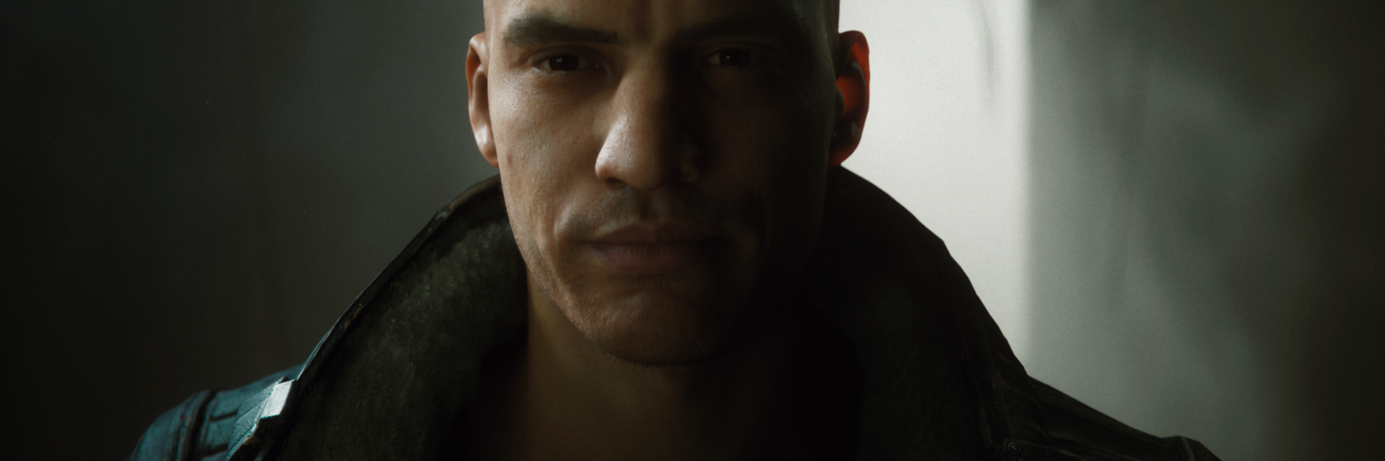
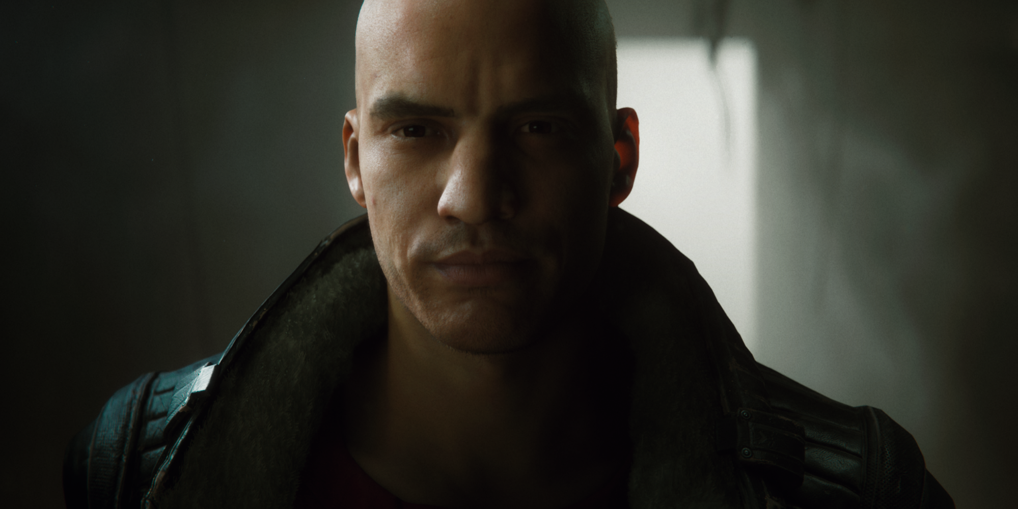
My name is Lasse Jon Fuglsang Pedersen, and I am a Senior Software Engineer on the Unity Demo Team. During the production of The Heretic, one of the things I worked on is the set of technical solutions that drive the face of Gawain, the digital human in the film.
This work was recently released as a standalone package on GitHub. In this blog post I will discuss some of the features of the package and share some insights into the development process behind those features.
Facial animation
One of the goals for the digital human in The Heretic was to attempt to avoid the uncanny valley in terms of facial animation, while still taking a realistic approach to the character as a whole. To match the actor’s performance as closely as possible, we decided to try using 4D capture data (a 3D scan per frame of animation) for the animation of the face mesh, which would then at least have the potential to be geometry-accurate to the actor’s facial performance (where not obstructed).
Using 4D capture data brought many interesting new challenges, as Krasimir Nechevski, our animation director, explains in more detail in this previous blog post. A lot of effort went into figuring out how to process and tweak the captured data, and then actually doing that, to get it into a state that we were happy with for the film.
Notes on processing
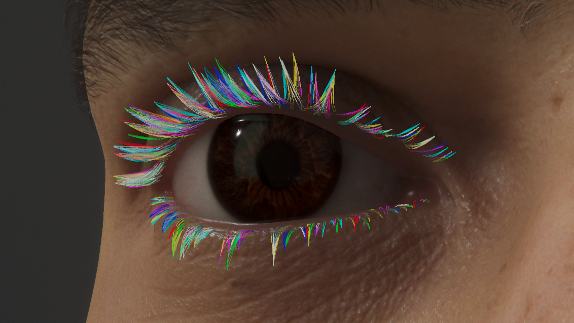
As an example, one of the issues we had was related to the geometry of the eyelids. Because eyelashes partially obstructed the eyelids during capture, the captured data also contained some influence from eyelashes, which manifested itself as noise in those regions. As a result, the geometry of the eyelids was inaccurate and jittery, and this meant that we had to find a way to reconstruct the geometry in those regions.
Jittery geometry near the eyelids
The issue with the eyelid geometry was apparent quite early in the process, so as part of working on the importer for just getting the data into Unity, we also experimented with region-specific noise reduction and reconstruction, using differential mesh processing techniques. Specifically, we would perform noise reduction by smoothing the regional change in curvature over time, and we would perform reconstruction by transplanting the curvature of a (clean) base mesh onto each damaged region of each frame of the captured sequence.
Denoising and transplanting geometry near the eyelids
While the results were fairly robust, we felt they were unfortunately also a bit too synthetic when compared to the original data: The eyelids, while more stable, lost some of the original motion that effectively made them feel human. It became clear that we needed a middle ground, which might have required more research than we realistically had time for. So when an external vendor offered to tackle the reconstruction work, that was an easy choice. The GitHub package, however, includes the internal tools originally written for denoising and region transplant, as they might be useful as a learning resource.
Fitting the wrinkles
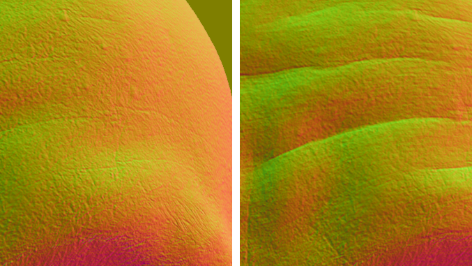
Another issue we had was that of fine surface details, or rather the lack of fine surface details, due to the resolution of the target face mesh: The face mesh of Gawain has ~28,000 vertices, and this was not sufficient for geometrically representing the fine wrinkles of the actor’s performance, much less the stretching of pores in the skin. Even if the raw 4D data had some of those details, we were not able to keep them after processing the data to fit the vertex budget of the mesh we were deforming and rendering. We considered baking a normal map per frame, but that would have required quite some space on disk, which we wanted to conserve.
To handle the fine surface details, we decided to try to couple the geometry of the imported sequence with the pose-driven feature maps from a blend shape-based facial rig from Snappers Systems. The pose-driven feature maps from the facial rig contained the type of surface detail that we were missing in the imported sequence, like wrinkles and the stretching of pores. So the basic idea was this: If we could figure out which combination of blend shapes would best approximate each frame of 4D, then we should also be able to use those weights to drive just the pose-driven feature maps (excluding the deformation from the blend shapes), for added surface detail during 4D playback.
Finding a good way to fit the blend shapes to the 4D was a two-step process. The first step was a least squares approach, for which we put the problem in matrix form. If we write up all the blend shapes (which are deltas to the base mesh) as one large matrix A, where each column holds the delta of a single blend shape, then the composite delta is given by Ax = b, where x represents the weights of the individual blend shapes.
Solving for x is often not possible, due to A often not being invertible (in our case it is not invertible, simply because it is not square). It is, however, often possible to arrive at an approximate solution x*, by formulating the problem slightly differently: Using the so-called normal equation ATAx* = ATb, we can write the least squares solution as x* = (ATA)-1ATb, which then only requires that A has linearly independent columns. Working with blend shapes, we need to filter the included shapes to ensure that they are linearly independent, and then we can work towards an approximate solution: We precompute (ATA)-1AT for the filtered blend shapes of the rig, and then we plug in the delta b for each frame of 4D, to compute x* (the fitted weights) for each frame of 4D.
While the unconstrained least squares approach outlined above was nice for building a basic understanding of the problem, it did not work well for us in practice. The solution would also sometimes contain negative weights, to get closer overall to the given 4D frame. But the facial rig expected blend shapes to be only added, not subtracted, so the fitted weights effectively exceeded the constraints of the rig, and therefore it was not always possible to translate them into meaningful wrinkles.
In other words, we needed a non-negative solution to get the wrinkles that we wanted. To compute the non-negative solution, we used a subset of a third-party library called Accord.NET, which contains an iterative solver specifically for the non-negative least squares problem. After having dissected the problem and tested the unconstrained solution, we already had the filtered blend shape matrix A and the desired delta b, and it was straightforward to plug those into the iterative solver to obtain a non-negative set of fitted weights for each frame of 4D.

As a side note, we also experimented with computing the fitted weights based on mesh edge lengths as well as based on edge curvatures, rather than base mesh position deltas. If we had not been able to remove the head motion from the 4D data, we would have needed to use one of these paths to make the fit independent of the head motion. For Gawain, we ended up fitting the position deltas, but the other two options are still available in the package.
Workflow in Unity
Before getting the 4D data into Unity, it is important to note that we first rely on external tools to ensure that the 4D capture data is turned into a sequence of meshes (delivered as .obj) with frame-to-frame matching topology. The topology also needs to match that of the target mesh for which the data is imported. (See Krasimir Nechevsky’s blog post for more details.)
Then, to get the preprocessed 4D data into Unity and turn it into a runtime-ready clip, the package provides a custom type of asset, that we call the SkinDeformationClip. Once created, a SkinDeformationClip exposes the tools for importing (and optionally processing) a segment of 4D data, which can be specified as either a path to .obj files anywhere on disk (removing the need for including intermediate assets in the project) or as a path to Mesh assets already within the project.
Creating a clip asset and importing the 4D frames from .obj
After configuring the SkinDeformationClip asset, click the Import button in the Inspector to start importing and processing the frame data. Note that if either mesh processing or frame fitting is enabled on the asset, this can take a while. After the import finishes, the clip asset now stores the imported frame intervals, fitted weights, etc., but not the final frame data. The frame data is stored in a separate binary next to the asset, so that we can stream the data efficiently from disk during playback.
Once imported, you can play back the asset by dragging it onto a custom type of track for Unity Timeline, called the SkinDeformationTimeline. This type of track specifically targets a SkinDeformationRenderer component, which then acts as an output for the clip data on the track. The video below illustrates the process of sequencing and playing back the imported 4D data on the Timeline.
Playing back the clip asset using Unity Timeline
Through using the custom track and the SkinDeformationRenderer, it is possible to also blend multiple 4D clips, which allows artists to get creative with the data. For example, for the first part of The Heretic we used only a very short segment of 4D data, which contained only a test phrase and the three-second performance for the initial close-up. And yet, through careful reuse (cutting, scaling, and blending), it was possible to use this same single clip for the remaining facial animation in the entire first part of the film.
Skin attachments
Since we chose to use the 4D data directly for the facial animation, we could not rely on bone-weighted skinning or blend shapes to resolve the positions of important secondary features, such as eyelashes, eyebrows, or stubble. Basically, we needed a way to resolve these features as a function of the animated face mesh itself.
Technically, we could have loaded the processed 4D data into an external tool, modeled and attached the secondary features there, and baked out additional data for all of them. However, streaming in tens of thousands of extra vertices per frame was not viable in terms of storage, and the result also would not have been very dynamic. We knew that we needed to iterate on the 4D data throughout the production, so our solution would have to react to these iterations without a tedious baking step.
To solve this problem, the Digital Human package has a feature that we called the skin attachment system. This system basically allows attaching arbitrary meshes and transforms to a given target mesh at editor time, and then resolves them at runtime to conform to the target mesh, independent of how the target mesh is animated.
For the digital human in The Heretic, we used the skin attachment system primarily to drive the eyebrows, eyelashes, stubble and logical markers in relation to the skin. We also used the system to attach the fur mesh to the jacket, as Plamen Tamnev, Senior 3D Artist on the team, has described in more detail.
To illustrate how to use the system, here are the steps to attach, for example, the transform of a GameObject to the face of Gawain:
- Add a SkinAttachment component.
- In the Inspector, set the type of attachment to Transform.
- In the Inspector, point the target field to the SkinAttachmentTarget on the face.
- Move the transform to the desired relative location.
- Click the Attach button in the Inspector.
Placing and attaching a transform
How it works
Under the hood, when clicking the Attach button to attach a transform, the system uses the position of the transform to query a k-d tree for the closest vertex on the face mesh. The closest vertex is then used to identify all incident triangles to the closest vertex, and for each of the incident triangles, the system generates a local pose given the current position of the transform, resulting in a set of local poses for the transform.

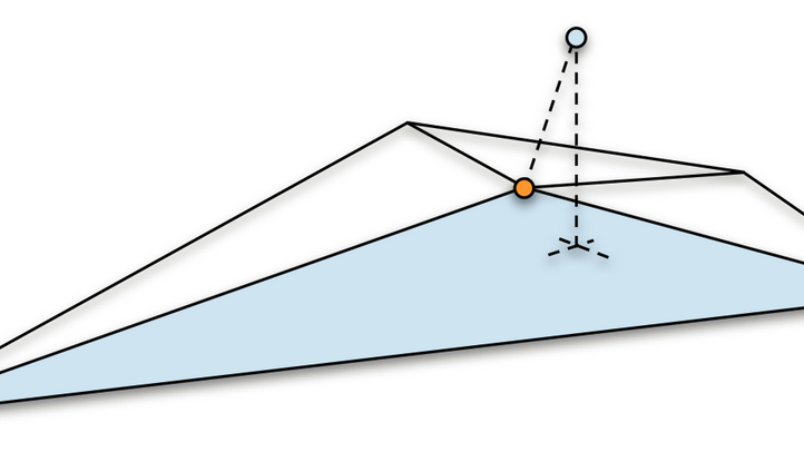
Each local pose is a projection of the attached point onto the plane of a given triangle, and it contains the vertex indices of the triangle, the normal distance from the attached point to the triangle, and the barycentric coordinates of the projected point.

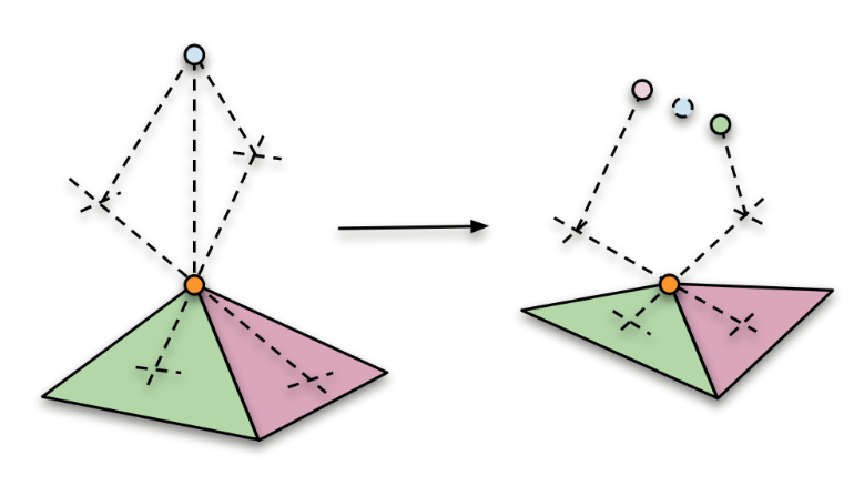
The reason that we generate multiple local poses for each attached point, rather than just for a single triangle, is to support points that do not belong to any particular triangle in the mesh. This is the case for some of our hair cards, for example, which float slightly above the mesh. To resolve the attached point based on multiple local poses, we first unproject the local pose for each triangle separately, and then average the results weighing by triangle area.
Once generated, the local poses are stored in a large continuous array, along with all the other local poses for all the other attachments to the face. Each attachment keeps a reference into this data, along with a checksum, as a safety measure in case the underlying data is modified by other means.
The process of attaching a mesh is very similar to that of a transform, just many times over. When attaching a mesh, the system simply generates a set of local poses for each vertex in the mesh, rather than for the single position of a transform.
Eyebrows attached using the regular mesh mode
For meshes, there is also a secondary attachment mode called MeshRoots: With this mode, the system first groups the mesh into islands based on mesh connectivity, and then finds the “roots” of each island in relation to the face mesh. Finally, it attaches every vertex within each island, in relation to the closest root within the island. The MeshRoots mode is necessary for some use cases, because it ensures that the individual islands stay rigid. For example, the eyelashes are attached in this way, while the eyebrows are not. This is because the hair cards for the eyebrows are mostly flush with the skin and expected to deform, while the hair cards for the eyelashes are expected to maintain shape.

At runtime, the system takes care that the positions and vertices of the attachments (transforms as meshes) are continuously updated to conform to the face mesh. Every frame, the final output state of the face mesh is calculated and used in combination with the known local poses to resolve all positions and vertices in relation to the skin. The image below illustrates the density of the attachments we used for Gawain.

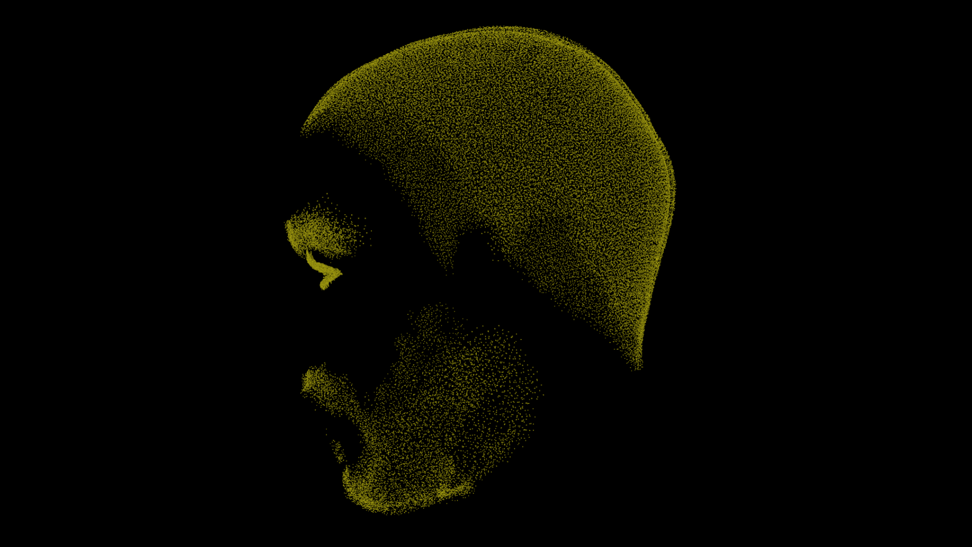
The runtime resolve is accelerated by the C# Job System and the Burst Compiler, which enables it to handle a relatively large amount of data. As an example, for the face of Gawain, the resolve jobs were collectively responsible for evaluating hundreds of thousands of local poses every frame, to resolve the secondary features of the face.
Shaders and rendering
When work started on the Digital Human package as a standalone release, one of the primary goals was to transition everything rendering-related to a strictly unmodified version of the High Definition Rendering Pipeline (HDRP), to ensure better upgradeability through new HDRP features for extensibility.
For context: At the time when we started prototyping the visuals for The Heretic, we were still missing some rather general features in HDRP for extensibility. We did not yet have a sensible way of writing custom upgradeable shaders, and we did not yet have a way to inject custom commands during a frame, e.g., for a custom rendering pass.
As a result, the custom shaders for the digital human (and several other effects in the film) were initially prototyped as direct forks of existing materials in HDRP, which at the time was still in Preview and still undergoing major structural changes. Many of the custom shaders also required core modifications to HDRP, which contributed to making upgrades often difficult. Thus, we were generally on the lookout for more extensibility features in HDRP, so that we would be able to reduce the number of customizations.
Therefore, creating the Digital Human package involved transitioning those then-necessary customizations to use the current-day extensibility features now provided by HDRP. This meant porting the digital human custom shaders to Shader Graph, using the HDRP-specific master nodes, and using the CustomPass API for executing the necessary custom rendering passes. Also, thanks to Unity’s Lead Graphics Programmer Sebastien Lagarde and a team at Unity Hackweek 2019, HDRP gained the Eye Master node, which was feature-compatible with the custom work previously done for The Heretic and therefore a great help in porting the eyes.
In the following sections I will go over the resulting shader graphs for skin, eyes and teeth, that can all be found in the package. There is also a shader graph for hair in the package, but it is mostly a pass-through setup for the Hair master node.
Skin
In general, the skin shader relies heavily on the built-in subsurface scattering feature of HDRP, which readily enables artists to author and assign different diffusion profiles to emulate various materials, including different types of skin. The skin graph itself uses the StackLit master node, in order to provide artists with two specular lobes (a setup commonly used for skin and not supported by the Lit master node), and for this reason the skin shader is forward-only.

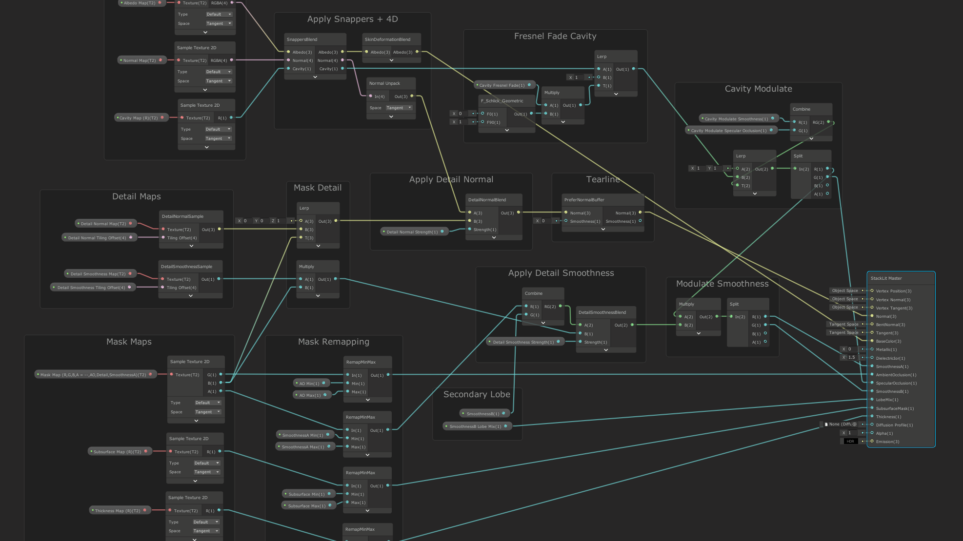
For the two specular lobes, the primary smoothness value is provided via a mask map, similar to the regular Lit shader, while the secondary smoothness value is exposed as a tweakable constant in the material inspector. Similar to the regular Lit shader, the mask map also allows artists to control an ambient occlusion factor, as well as the influence of two detail maps: one for detail normals and one for detail smoothness, where the detail smoothness affects both the primary and the secondary smoothness value.
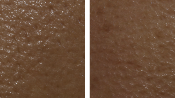
In addition to the regular mask map, the skin shader also accepts a cavity map (single channel texture, with lower values in cavities), which can be used to control a specular occlusion factor and/or reduce smoothness in small cavities, such as pores in the skin. The influence of the cavity map can also optionally be blended out at grazing angles, to emulate the effect of small cavities being hidden from view at grazing angles.


The skin shader also contains support for pose-driven features (e.g., wrinkles) from the specific Snappers facial rig that we used for Gawain. In the skin graph, this functionality is encapsulated in a custom function node, which has some hidden inputs that are not visible in the graph itself. These hidden inputs are driven by the SnappersHeadRenderer component in the package, which needs to be placed on the same GameObject as the SkinnedMeshRenderer that uses the shader.

Another curious node in the skin graph is related to the tearline setup, which I will explain a bit later, following the eyes section. Basically, to allow the tearline setup to modify the normals of the skin, we have to compute and store the normals during depth prepass, and then specifically sample them again in the forward pass (instead of recomputing them, which would discard the intermediate processing).
Eyes
The custom eye shader for The Heretic was a collaboration with Senior Software Engineer Nicholas Brancaccio, who contributed some of the initial work, including the two-layer split lighting model, and the implementation of the evaluation function for the occlusion near the eyelids. For the Digital Human package, some of that previously custom functionality has moved to the Eye Master node in HDRP, which the eye graph uses as an output.

The eye shader effectively models the eye as a two-layer material, where the first layer is used to describe the cornea and fluids at the surface, and the second layer is used to describe the sclera and the iris, visible through the first layer. Lighting is split between the two layers: specular lighting is evaluated exclusively for the top layer (representing cornea and surface fluids, which are more glossy), while the diffuse lighting is evaluated only for the bottom layer (iris and sclera).
Unobstructed view of the eyeball and a moving point light
Refraction in the cornea is handled internally, and the effect depends on both the input geometry and a couple of user-specified parameters. The eye input geometry needs to be a single mesh that describes only the surface of the eye, including the bulge of the cornea.
Then, given a user-specified cross-section that (roughly) describes where the surface of the cornea begins, we can determine during rendering if a given fragment is part of the cornea. If the fragment is part of the cornea, then we refract the view ray and intersect the refracted ray with a virtual plane that represents the iris. The iris plane is adjustable via an offset from the cornea cross-section, to enable artists to adjust the amount of visual parallax in the eye.
Orbiting the eyeball to illustrate refraction in cornea
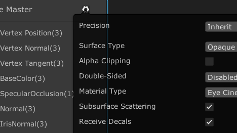
To evaluate the diffuse lighting in the iris, the eye shader also specifically provides an option for refracting the incident direction of light towards the iris, based on the currently rasterized fragment of the surface (cornea). While this does not give us proper caustics (we only accumulate the contribution from a single fragment at the refracting surface), artists can at least rely on the iris not appearing unnaturally in shadow when the eye is lit, e.g., from the side. The refracted lighting feature is now part of the Eye Master node, and it can be enabled through the Eye Cinematic mode.


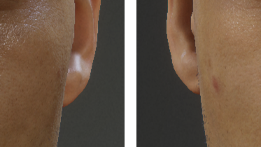
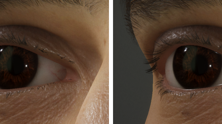
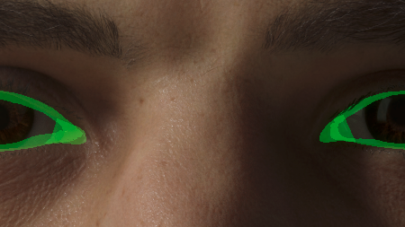
We model the occlusion near the eyelids using an anisotropic spherical Gaussian. The distribution is driven by four markers (transforms) that track the eyelids using the skin attachment system. Specifically, we use two markers to track the corners of the eye to form a closing axis, and then another two markers to track the upper and lower eyelids, which allows us to infer a closing angle. The closing axis and the closing angle are then used to generate the necessary basis vectors for evaluating the anisotropic spherical Gaussian at the surface of the eye. We use the result of this evaluation directly as an input to the ambient and specular occlusion factors on the Eye Master node, as well as to (optionally) modulate the albedo to artificially darken the occluded region.
Four markers drive an anisotropic spherical Gaussian for occlusion
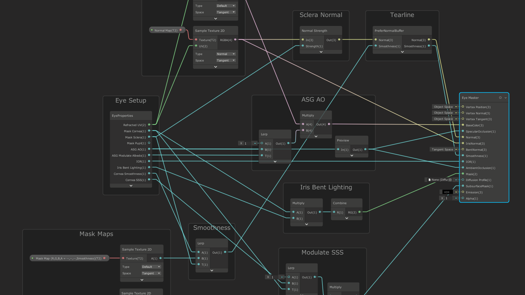
In the eye graph, most of the described features, including the refraction in the cornea and the occlusion near the eyelids, are facilitated by a single custom function node in the graph, labelled EyeSetup, which provides a number of readable outputs to the graph itself. Much like the custom function node for the facial rig in the skin graph, the custom function node in the eye graph uses hidden parameters that are not controlled through the material inspector, but through script code, due to the complexity and per-frame nature of those parameters. For the eye graph specifically, the hidden parameters are driven by the EyeRenderer component in the package, which needs to be placed on the same GameObject as the renderer that uses the shader, in order for the shader to produce a meaningful result.
The EyeRenderer component, in addition to computing and passing values to the shader, also provides some useful gizmos and handles that are meant to assist in setting up the eyes. For example, the gizmos allow artists to visualize and tweak the offset to the cross-section that defines the cornea region, or to inspect and slightly adjust the forward axis for the planar texture projection, in case the provided eye geometry is not exactly facing down the z-axis.
Tweaking the eye using handles in the scene view
Lastly, like in the skin graph, in the eye graph we also have a node that handles the integration with the tearline setup: Normals and smoothness are written during depth prepass, and then sampled again during the forward pass.
Tearline
To reconstruct the tearline (the wetness between the eyes and the skin), we rely on the HDRP CustomPass API, which allows applications to inject custom rendering work at certain stages during a frame.
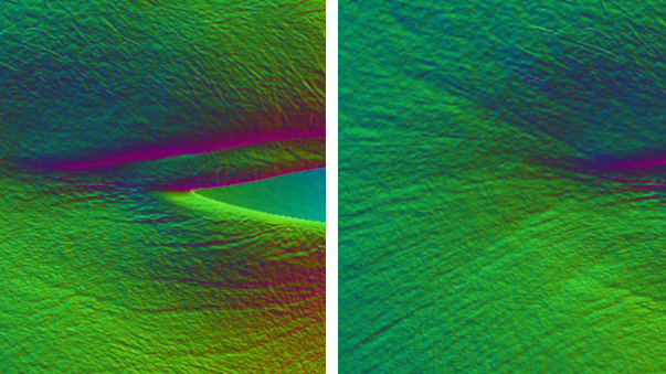
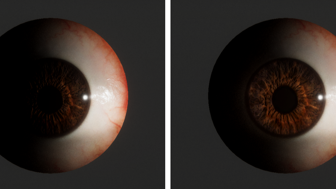
Using a custom pass that operates on the contents of the HDRP normal buffer (which holds both normal and smoothness data), we blur the normals and smoothness values in specific screen space regions on the face (e.g., where the eyes meet the skin). Since the skin and the eyes are forward-only materials, we also had to insert specific nodes in those graphs to ensure that they specifically sample the result during the forward pass.

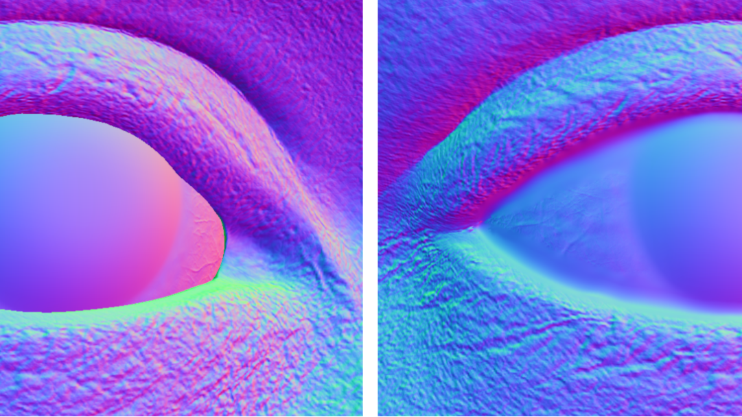
Creating a smooth transition in the normal buffer helps visually bridge the two surfaces. In combination with a high smoothness value in the region, this setup will often result in a specular highlight appearing in-between the two materials, which effectively makes the tearline region appear wet.

To mark the regions where the blurring should occur, we use a simple setup of masking decals that are placed in a specific user layer and never render any color to the screen (except for debugging purposes). By placing the decals in a specific user layer, we can more easily filter and render them exclusively in a custom pass, which mostly just sets one of the HDRP user stencil bits. Once all the masking decals have been drawn into the stencil, then we effectively have a screen space mask for where to perform the blur. We also use this mask to avoid blurring past the edges of the desired blur regions, by dynamically shrinking the width of the blur kernel to the edge of the mask.

For the tearline of Gawain, a masking decal was authored specifically for each eye, to visually overlap both the eyelid and eyeball in the neutral face pose, and then attached to the skin using the attachment system. To support a small gap between the eyeball and the eyelid (as was evident with some of our 4D data), we also slightly exaggerated the geometry, so that it would have more inward-facing overlap with the eyeball.
Teeth
The teeth shader relies on many of the features of the Lit master node, including the subsurface scattering and the mask for clear coat. Apart from using the existing features of Lit, the shader also adds a custom type of attenuation that we use to smoothly darken the interior of the mouth, based on the current size of the mouth opening.

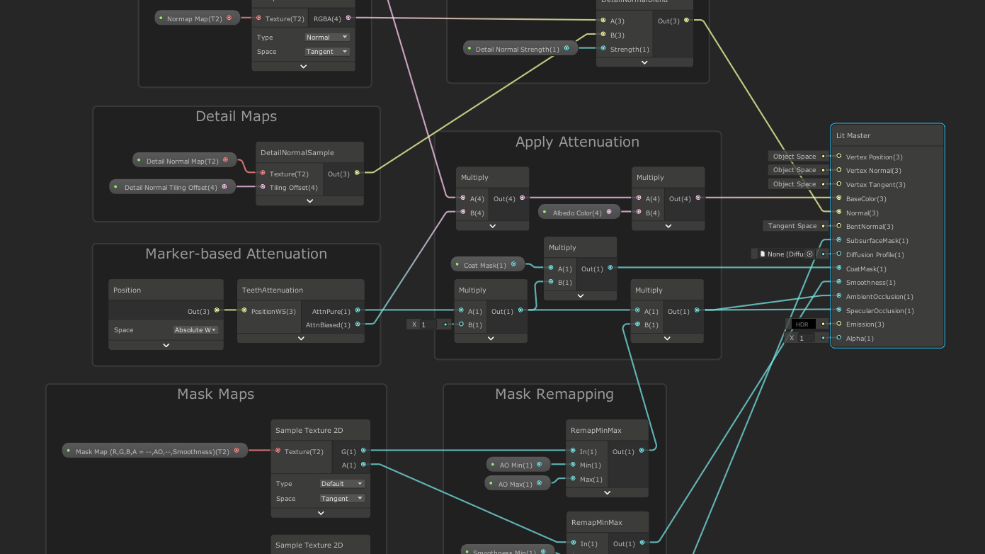
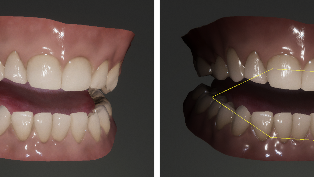
To approximate the current size of the mouth opening, we place six markers near the opening of the mouth, to form a polygon that roughly approximates the interior contour of the lips. For Gawain, we used the skin attachment system to drive these markers, so that they will follow the lips regardless of how the face mesh is animated.
During rendering, we start by passing this polygon to the shader, and then in the shader we project the polygon onto the unit hemisphere around the current fragment to obtain a spherical polygon. Intuitively, this spherical polygon then tells us something about how much of the exterior is visible through the mouth opening, from the point of view of the current fragment.
Visualizing the spherical polygon on a sphere in the mouth
To darken the interior of the mouth, we then simply use the area of the spherical polygon, in relation to the area of the unit hemisphere, as a non-physical attenuation term (ignoring the cosine). Specifically, we attenuate the existing ambient and specular occlusion factors, the coat mask, and the albedo, before passing these to the Lit master node in the graph.

Similar to the skin and eye graphs, the teeth graph also contains a custom function node whose inputs are not visible in the graph. For the teeth graph, the hidden inputs are provided by the TeethRenderer component in the package, which must be added to the same GameObject as the renderer that uses the shader.
Final notes
I hope this blog post has helped illustrate some of the challenges and work that went into creating the set of technical solutions for the face of Gawain.
If you want to explore or build on the tools that we are sharing, you can download the library from GitHub and use the technology in your own projects, including commercial productions. We would love to see what you make with it!
We’re sharing more learnings from the creation process behind this project on The Heretic landing page.
Is this article helpful for you?
Thank you for your feedback!
- Unity Labs
- Copyright © 2024 Unity Technologies